- Tìm kiếm nhiều:
- AI Computer
- Raspberry Pi
- NVIDIA Jetson
- Máy tính nhúng
- Màn hình LCD ....


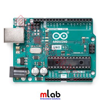
Sản phẩm được nhập khẩu chĩnh hãng từ Arduino Made in Italy
Hỗ trợ kỹ thuật trong quá trình sử dụng
Xuất hóa đơn VAT cho cá nhân, đơn vị có nhu cầu
Sản phẩm được bảo hành 12 tháng
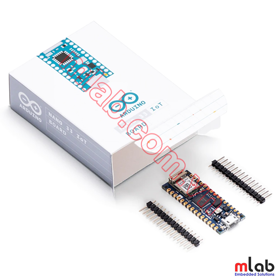
 Arduino Nano 33 IoT allows you to build your next smart project. Ever wanted an automated house? Or a smart garden? Well, now it’s easy with the Arduino IoT Cloud compatible boards. It means: you can connect devices, visualize data, control and share your projects from anywhere in the world. Whether you’re a beginner or a pro, we have a wide range of plans to make sure you get the features you need.
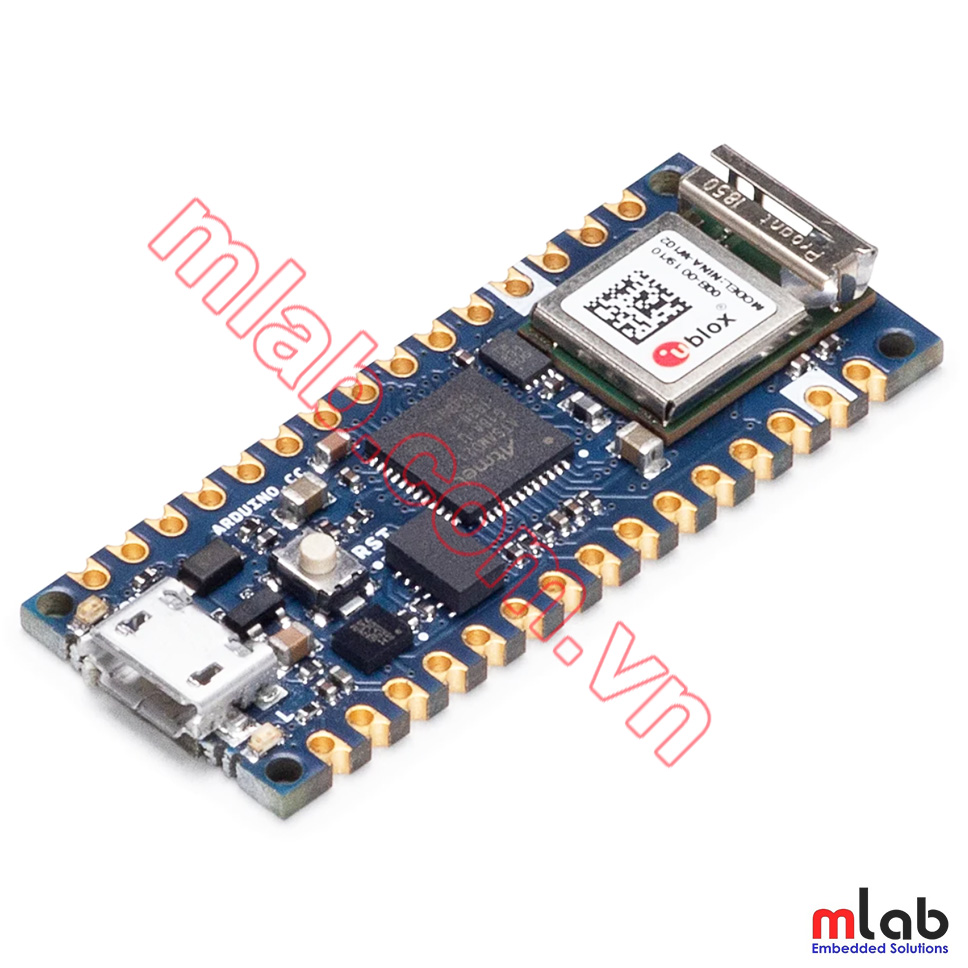
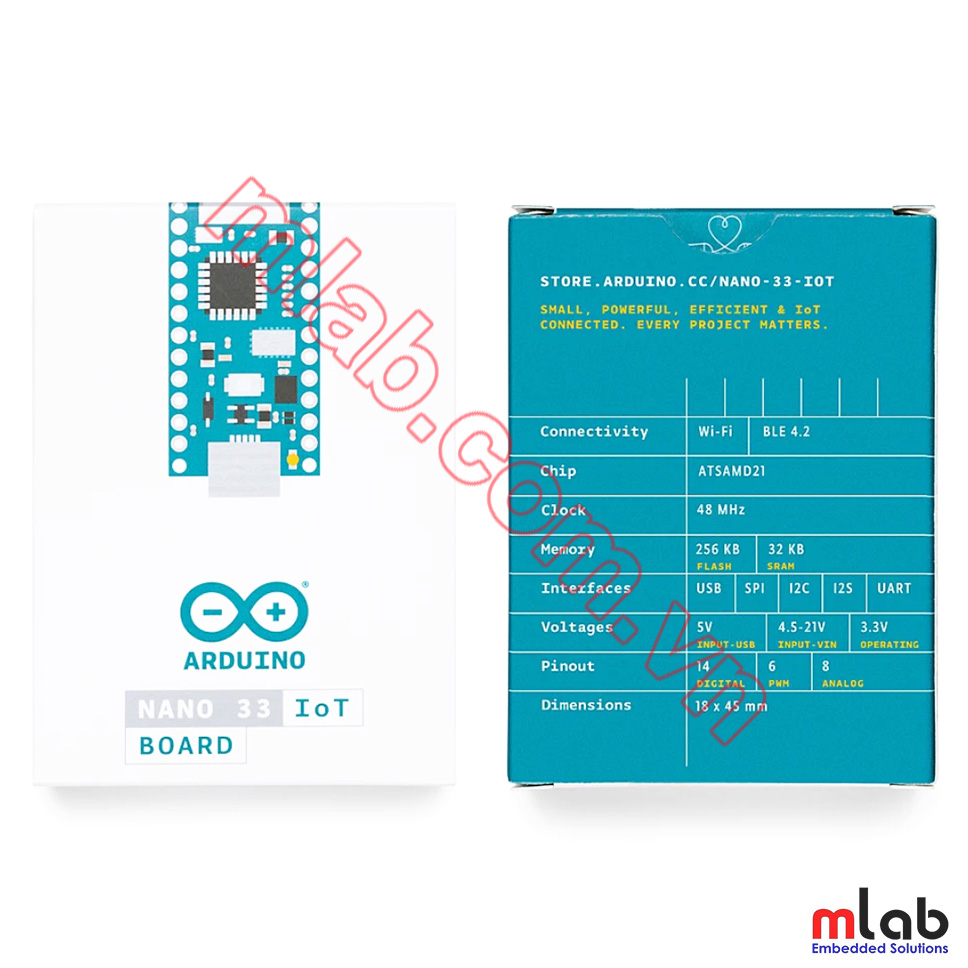
The Arduino Nano 33 IoT is the easiest and cheapest point of entry to enhance existing devices (and creating new ones) to be part of the IoT and designing pico-network applications. Whether you are looking at building a sensor network connected to your office or home router, or if you want to create a Bluetooth® Low Energy device sending data to a cellphone, the Nano 33 IoT is your one-stop-solution for many of the basic IoT application scenarios.
The board's main processor is a low power Arm® Cortex®-M0 32-bit SAMD21. The WiFi and Bluetooth® connectivity is performed with a module from u-blox, the NINA-W10, a low power chipset operating in the 2.4GHz range. On top of those, secure communication is ensured through the Microchip® ECC608 crypto chip. Besides that, you can find a 6 axis IMU, what makes this board perfect for simple vibration alarm systems, pedometers, relative positioning of robots, etc.
At Arduino we have made connecting to a WiFi network as easy as getting an LED to blink. You can get your board to connect to any kind of existing WiFi network, or use it to create your own Arduino Access Point. The specific set of examples we provide for the Nano 33 IoT can be consulted at the WiFiNINA library reference page.
It is also possible to connect your board to different Cloud services, Arduino's own among others. Here some examples on how to get the Arduino boards to connect to:
Note: while most of the above-shown examples are running on the MKR WiFi 1010, both boards have the same processor and wireless chipset, which means it will be possible to replicate them with the Nano 33 IoT.
The communications chipset on the Nano 33 IoT can be both a Bluetooth® and Bluetooth® Low Energy client and host device. Something pretty unique in the world of microcontroller platforms. If you want to see how easy it is to create a Bluetooth® central or a peripheral device, explore the examples at our ArduinoBLE library.
The Nano 33 IoT is a dual processor device that invites for experimentation. Hacking the WiFiNINA module allows you to, for example, make use of both WiFi and Bluetooth® and Bluetooth® Low Energy at once on the board. Yet another possibility is having a super-lightweight version of linux running on the module, while the main microcontroller controls low level devices like motors, or screens. These experimental techniques, require advanced hacking on your side. They are possible via modifying the module's firmware that you can find at our github repositories.
BEWARE: this kind of hacking breaks the certification of your WiFiNINA module, do it at your own risk.
The Arduino Nano 33 IoT is based on the SAMD21 microcontroller.
| Microcontroller | SAMD21 Cortex®-M0+ 32bit low power ARM MCU (datasheet) |
| Radio module | u-blox NINA-W102 (datasheet) |
| Secure Element | ATECC608A (datasheet) |
| Operating Voltage | 3.3V |
| Input Voltage (limit) | 21V |
| DC Current per I/O Pin | 7 mA |
| Clock Speed | 48MHz |
| CPU Flash Memory | 256KB |
| SRAM | 32KB |
| EEPROM | none |
| Digital Input / Output Pins | 14 |
| PWM Pins | 11 (2, 3, 5, 6, 9, 10, 11, 12, 16 / A2, 17 / A3, 19 / A5) |
| UART | 1 |
| SPI | 1 |
| I2C | 1 |
| Analog Input Pins | 8 (ADC 8/10/12 bit) |
| Analog Output Pins | 1 (DAC 10 bit) |
| External Interrupts | All digital pins (all analog pins can also be used as interrput pins, but will have duplicated interrupt numbers) |
| LED_BUILTIN | 13 |
| USB | Native in the SAMD21 Processor |
| IMU | LSM6DS3 (datasheet) |
| Length | 45 mm |
| Width | 18 mm |
| Weight | 5 gr (with headers) |
The Arduino Nano 33 IoT is open-source hardware! You can build your own board using the following files:
EAGLE FILES IN .ZIP SCHEMATICS IN .PDF FRITZING IN .FZPZ DATASHEET IN .PDF

Download the full pinout diagram as PDF here.
Download the Fritzing part here.
On the bottom side of the board, under the communication module, debug signals are arranged as 3x2 test pads with 100 mil pitch. Pin 1 is the bottom left one with the USB connector on the left and the test pads on the right. Check the downloadable pinout diagram for the exact configuration.
Some of the NINA W102 pins are connected to the 15+15 pins headers/pads and can be directly driven by the module's ESP32; in this case it is necessary that the SAMD21 corresponding pins are aptly tri-stated. Below is a list of such signals:
| SAMD21 Pin | SAMD21 Acronym | NINA Pin | NINA Acronym | Header Description |
| 48 | PB03 | 8 | GPIO21 | A7 |
| 14 | PA09 | 5 | GPIO32 | A6 |
| 8 | PB09 | 31 | GPIO33 | A5 / SCL |
| 7 | PB08 | 35 | GPIO5 / GPIO19 | A4 / SDA |